- Thiết Bị Khí Nén
- Thiết Bị Điều Khiển Từ Xa
- Thiết Bị Vệ Sinh
- Thiết Bị Điện Thông Minh
-
Thiết Bị Điện Đo Đếm
- Đồng Hồ Đo Tốc Độ
- Đồng Hồ Đo Lưu Lượng
- Đồng Hồ Đo Tần Số
- Cảm Biến Phân Biệt Màu
- Đồng Hồ Đo Áp Suất
- Đầu Cân Loadcell
- Cảm Biến Đo Khoảng Cách
- Đồng Hồ Đa Chức Năng
- Đồng Hồ Đo Dòng Điện Amper
- Đồng Hồ Đo Điện Áp Volt
- Biến Dòng Đo Lường
- Bộ Điều Khiển Nhiệt Độ
- Bộ Điều Khiển Độ Ẩm
- Bộ Điều Khiển Tụ Bù
- Bộ Đo Vòng Quay Encoder
- Bộ Đếm Counter
- Cảm Biến Báo Mức
- Cảm Biến Từ
- Cảm Biến Tiệm Cận
- Cảm Biến Quang
- Cảm Biến Điện Dung
- Cảm Biến Cửa Tự Động
- Cảm Biến Vùng
- Cảm Biến Áp Suất
- Công Tơ Điện
- Rờ Le Thời Gian
- Thiết Bị Điện Tự Động
- Thiết Bị Điện Đóng Cắt
- Thiết Bị Điện Bảo Vệ
-
Các danh mục khác
THƯƠNG HIỆU
-
- Vacon
- Qlight
- Biovin
- Lightstar
- Hyuphwa
- Deesys
- Italy
- Ching Hai
- Proface
- YPC
- TPC
- Sang-A
- Festo
- Ilec
- Carlo Gavazzi
- Lihhan
- LSE
- Saginomiya
- OBO
- Datalogic
- Dol
- Hoa Sen
- Weinview
- Toshiba
- Decom
- Done
- Connectwell
- Weintek
- Dixell
- Pumpman
- Fushin
- VMC
- Hanshin
- Arinco
- Candino
- Livar
- ELCO
- Optex
- Pepperl Fuchs
- Airtac
- Rockwell
- Phoenix Contact
- Eaton
- AB Home
- Bals
- Epviso
- Simon
- Hunonic
- Novus
- Weidmuller
- Hender
- Kimono
- Menekes
- CKC
- Lucky Star
- Telecrane
- Henjel
- Tayee
- Cadisun
- Việt Thái
- Deton
- Hatari
- Master
- ENDA
- Gic
- Philips
- Esbee
- Kentom
- CNTD
- Leipole
- Idec
- JLD
- Senko
- CET
- Donaifan
- Viviko
- Burkert
- Yato
- UNI-T
- LAP
- Osram
- Osung
- Osemco
- Vitzro
- Kyoritsu
- Letatwin
- Vinasino
- MDT
- Conotec
- Chin I
- Hawin
- ENC
- Delixi
- Oriental Motor
- SPG
- HBT
- Kael
- Danfoss
- Winpark
- KyungDong
- Sunny
- Drosseln
- Kripal
- Andawo
- Sinotimer
- Wecon
- Evertop
- Meanwell
- Tense
- Thuận Phong
- Kumwell
- Socoho
- Hyundai
- Sungho
- Koino
- YongSung
- Neoseal
- Wika
- Mennekes
- Havells
- Rạng Đông
- Ledvance
- Hwasan
- UNI-D
- Smartgen
- Top
- Pansong
- Fort
- RKC
- Siemens
- Moli
- Turck
- Hivero
- Meikosha
- Nanoco
- Iskra
- Elmark
- Bourns
- Elecnova
- Motec
- Minjin
- JYE
- Boxco
- Winsun
- Multron
- Dongwoo
- Rikq
- Shintec
- Honeywell
- Liva
- Elitech
- Fumak
- Lazico
- Kawasan
- SMC
- Toho
- Ecotran
- Littelfuse
- Kale
- Dona
- Enerlux
- Epcos
- Ducati
- Samwha
- Robben
- Yokogawa
- Emic
- ANV
- Anly
- Daco
- Lioa
- Parker
- Gale
- Fotek
- Autosigma
- Dolin
- Delta
- Nidec
- Sumo
- Veichi
- Invt
- Thinkvert
- Inovance
- Yaskawa
- HNC
- Led Tân Việt Điện
- Sino
- MPE
- Paragon
- Duhal
- Shizuki
- Chint
- Schneider
- ABB
- Mitsubishi
- Hitachi
- Fox
- Hager
- Himel
- KYE
- Autonics
- Keyence
- Omron
- Sick
- Vinakip
- Mikro
- SK
- Selec
- Shihlin
- Teco
- Panasonic
- LS
- Hanyoung
- Nuintek
- Hydra
- Fuji
- Bekonec
- PCE
- Delab
- JKN
- Taya
- Taihan
- Cadivi
SẢN PHẨM MỚI
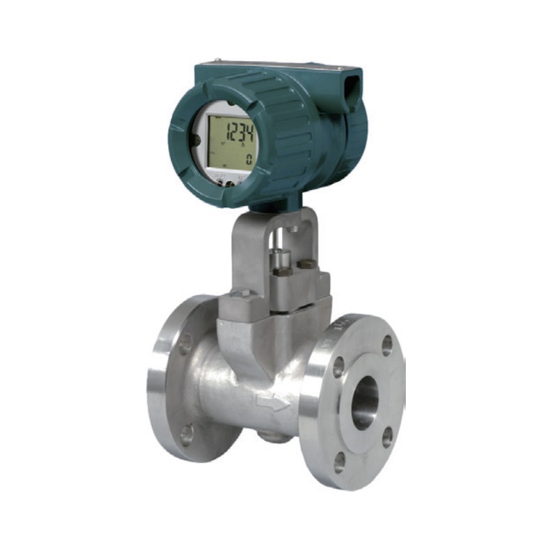
Đồng Hồ Lưu Lượng Vortex Flowmeter Yokogawa 1-1/2 inch DY040
- Tình trạng: Còn hàng
- Hãng sản xuất: Yokogawa
- Mã thiết bị: DY040
- Bảo hành: 12 Tháng
- Xuất xứ: Nhật Bản
| MODEL | DN mm |
PS* | PS·DN | ||
| (bar) | (MPa) | (bar·mm) | (MPa·mm) | ||
| DY015 | 15 | 420 | 42 | 6300 | 6300 |
| DY025 | 25 | 420 | 42 | 10500 | 10500 |
| DY040 | 40 | 420 | 42 | 16800 | 16800 |
| DY050 | 50 | 420 | 42 | 21000 | 21000 |
| DY080 | 80 | 420 | 42 | 33600 | 33600 |
| DY100 | 100 | 420 | 42 | 42000 | 42000 |
| DY150 | 150 | 420 | 42 | 63000 | 63000 |
| DY200 | 200 | 420 | 42 | 84000 | 84000 |
| DY250 | 250 | 420 | 42 | 105000 | 105000 |
| DY300 | 300 | 420 | 42 | 126000 | 126000 |
| DY400 | 400 | 250 | 25 | 100000 | 100000 |
BẢNG LỰA CHỌN MÃ HÀNG
| Model | Suffix Codes | Description |
| DY015 DY025 DY040 DY050 DY080 DY100 DY150 DY200 DY250 DY300 DY400 |
········································ ········································ ········································ ········································ ········································ ········································ ········································ ········································ ········································ ········································ ········································ |
Size 15 mm (1/2 inch) Size 25 mm (1 inch) Size 40 mm (1-1/2 inch) Size 50 mm (2 inch) Size 80 mm (3 inch) Size 100 mm (4 inch) Size 150 mm (6 inch) Size 200 mm (8 inch) Size 250 mm (10 inch) Size 300 mm (12 inch) Size 400 mm (16 inch) |
| Output Signal /Communication |
-D ···································· -E····································· -J····································· -F····································· -N ···································· |
4 to 20 mA DC, Pulse, BRAIN Communication 4 to 20 mA DC, Pulse, HART Communication *1 4 to 20 mA DC, Pulse, HART 5/HART 7 Communication *2 Digital communication (FOUNDATION Fieldbus protocol) *3 Remote type detector |
| Body Material *6, *7 |
A································ B································ X································ |
SCS14 A *4 CF8M *5 Others |
| Shedder bar Material *6, *7 |
L·························· B·························· E·························· X·························· |
Duplex Stainless Steel Stainless Steel Duplex Stainless Steel (for TIIS Approval) Others |
| Process Connection *8, *15 RF: Raised Face SF: Smooth Finish RJ: Ring Joint R13: DIN 2513 Type R13 |
AJ1 ··················· AJ2 ··················· AJ4 ··················· |
JIS 10 K Wafer JIS 20 K Wafer JIS 40 K Wafer |
| AA1··················· AA2··················· AA4··················· |
ANSI Class 150 Wafer ANSI Class 300 Wafer ANSI Class 600 Wafer |
|
| AD1··················· AD2··················· AD3··················· AD4··················· |
DIN PN10 Wafer DIN PN16 Wafer DIN PN25 Wafer DIN PN40 Wafer |
|
| BJ1 ··················· BJ2 ··················· BJ4 ··················· |
JIS 10K Flange(RF) JIS 20K Flange(RF) JIS 40K Flange(RF) |
|
| BA1··················· BA2··················· BA4··················· BA5··················· BA6··················· |
ANSI Class 150 Flange(RF) ANSI Class 300 Flange(RF) ANSI Class 600 Flange(RF) ANSI Class 900 Flange(RF) ANSI Class1500 Flange(RF) *16,17 |
|
| BS1··················· BS2··················· BS4··················· BS5··················· |
ANSI Class 150 Flange(RF, SF) ANSI Class 300 Flange(RF, SF) ANSI Class 600 Flange(RF, SF) ANSI Class 900 Flange(RF, SF) |
|
| BD1··················· BD2··················· BD3··················· BD4··················· |
DIN PN10 Flange(RF) DIN PN16 Flange(RF) DIN PN25 Flange(RF) DIN PN40 Flange(RF) |
|
| CA4··················· CA5··················· CA6··················· |
ANSI Class 600 Flange(RJ) ANSI Class 900 Flange(RJ) ANSI Class1500 Flange(RJ) *16,17 |
|
| FD1··················· FD2··················· FD3··················· FD4··················· |
DIN PN10 Flange(R13) DIN PN16 Flange(R13) DIN PN25 Flange(R13) DIN PN40 Flange(R13) |
|
| Electrical Connection *9 |
-0·················· -2·················· -4·················· |
JIS G 1/2 Female ANSI 1/2 NPT Female *10 ISO M201.5 Female |
| Indicator *11 |
D ·············· N ·············· |
With Indicator None Indicator, Remote type detector |
| Options | / | Read Option Specifications |
*1: Output signal code ‘-E’: HART 5. (Output signal code ‘-J’ is recommended for HART communication.)
*2: Output signal code ‘-J’: HART 5 or HART 7 selectable. Specify HART 5 or HART 7 when ordering.
*3: For FOUNDATION Fieldbus protcol, read GS 01F06F01-01EN. For Fieldbus communication type, there are not setting keys on the display board.
*4: In case of A (SCS14A), the process connection is available for JIS (AJ, BJ)
*5: In case of B (CF8M), the process connection is available for ANSI (AA, BA, BS, CA) and DIN (AD, BD, FD). In case of process connection code BA6 or CA6, body material is F316.
*6: Read Table 1.
*7: Users must consider the characteristics of selected wetted parts material and the influence of process fluids. The use of inappropriate materials can result in the leakage of
corrosive process fluids and cause injury to personnel and/or damage to plant facilities. It is also possible that the instrument itself can be damaged and that fragments from the
instrument can contaminate the user’s process fluids.
Be very careful with highly corrosive process fluids such as hydrochloric acid, sulfuric acid, hydrogen sulfide, sodium hypochlorite, and hightemperature steam (+150°C [+302°F] or
above). Contact Yokogawa for detailed information of the wetted parts material.
*8: Read Table 2.
*9: In case of an explosion protect type, it depends for an electrical connecion on the kind of an explosion protect type. Read “n OPTION SPECIFICATIONS (FOR EXPLOSION
PROTECTED TYPE)”
*10: In case of /FF1 or /CF1, CF11, /KF2, /KS2, /SF2, /SS2 the screw length is deeper than ANSI standard for 0.5 to 2 threads.
*11: Indicator is not available for remote type detector.
*12: DYA-/MV and DY-N***/MV should be combined.
*13: One set of end finish part is attached.
*14: DYC Signal Cable can be used up to 30m. When you divide the cable below 30m, select the Cable End code [-0].
*15: In case of the process connection FD, the Option code /LT is not avaiable.
*16: In case of BA6 or CA6, combination with the option code/R1 is mandatory(DY025/R1 to DY150/R1), and it is not available to combine with option code /HT, /LT and /MV.
*17: In case of DY040-XXA6-/R1/HY or /NC, maximum working pressure is flange rating times 0.8.